James Larkby-Lahet
A previous version of this article was republished on kbd.news
Low Power Improved Square Matrix
This post proposes a modification to the improved square keyboard matrix in order to support a low power wake-on-keypress mode, which has been a deficiency of this design until now.
Keyboard Matrix Background
an illustration of a keyboard matrix, borrowed from dovenyi’s KBD.news duplex matrix explainer
A keyboard matrix is a way of detecting key presses without wiring each switch to its own GPIO pin on the micrcocontroller. This is important because pins are a somewhat scarce resource, and when higher pin count versions of a given chip are available they are more expensive. The basic approach is to arrange switches in a grid with one side connected to a row wire and one to a column wire. One pin is assigned to each row and column wire. Either rows or columns are chosen as inputs and the other as outputs. One output pin is set high at a time and then the inputs are read to detect closed switches (keypresses). This is known as scanning the matrix. To properly detect multiple simultaneous keypresses, each switch must be wired in series with a diode so that current can’t flow “backward” through switches assigned to different output pins than the currently active one, which could otherwise create ghost keypresses.
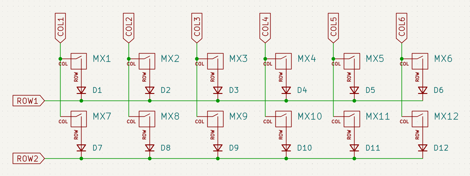
The Matrix, Evolved
an improved square matrix, from KBD.news
The improved square (or round-robin) matrix is a method of sensing switch activations using the fewest number of GPIO pins possible (as far as we know). The key insight is that rather than statically assigning pins as inputs or outputs (and rows and columns), we can dynamically reconfigure them to serve both roles, with the caveat that a switch cannot have the same pin as both input and output. The extra connectedness of the square matrix, compared to a traditional matrix, also means more opportunities for ghosting (see the precursor write up on the round robin matrix for details). This can be addressed with larger voltage drops either by using diodes with higher values, or by doubling up on the 1N4148 diodes traditionally used. The improved version observes that rather than using 2 diodes per switch, we can ‘factor out’ one diode and instead use one diode per GPIO pin, between input (or column, in these diagrams) segment and the output (or row) segment.
Low Power Mode
Pete Johanson raised the difficulty in supporting a low power keyboard mode at the time of the original KBD.news post about the round robin matrix. He has since expanded on it as part of his excellent piece on designing keyboards for wireless connectivity and low power use.
Power use is a significant concern for battery-powered wireless keyboards, which aim to extend their battery life as long as possible. Keyboards spend a significant amount of time idle and therefore significant power can be saved by putting the CPU to sleep. However, there must be a way to detect when a key is pressed and wake the sleeping keyboard controller back up.
The approach used on a traditional matrix, which is illustrated in detail in Pete’s post, is to enable interrupts on the input pins and to set all output pins to high at once. This ensures that if any key is pressed, the CPU will be awoken. Note that because all the output pins are high, the interrupt will not be informative as to which key was pressed, so the keyboard must resume scanning the matrix as usual. Interrupts are not a substitute for scanning a matrix, just a means to resume it.
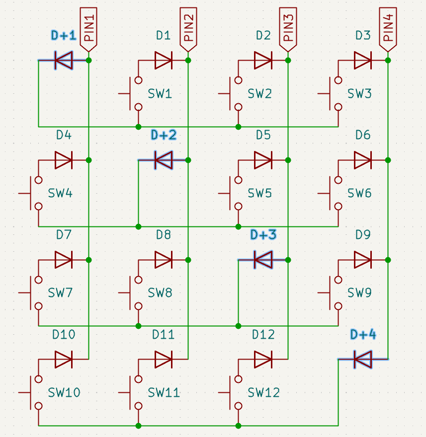
Low Power Mode for the Improved Square Matrix
With the improved square matrix, its easy to see how to listen for keypresses: we must treat all pins as inputs, pulling them low and enabling interrupts. However, this leaves us unsure about the other part: how do we connect the other side of the switches to a detectable voltage?
additional wire and diodes on the left side
The improved matrix makes this possible, both to visualize and to implement, by separating the output segments (rows, in this illustration) from the input segments (columns) by a diode, with the GPIO pins on the input side. We can add a single additional pin to supply a voltage to all the output segments, using diodes to prevent them from becoming connected during normal matrix scanning.
With the additional pin pulled low, scanning can be done as normal. When it is time for the CPU to sleep, we pull the new pin high and configure the other pins as low inputs with interrupts enabled. Any keypress will wake the CPU, as with the traditional matrix low power mode.
We don’t need to worry that the new diodes will drop the voltage below the voltage threshold, as they substitute for the diodes the improved matrix introduced to combat ghosting. If the matrix registers keypresses correctly, then the low power mode will as well.
This technique does require an additional GPIO pin, but given the large number of pins saved compared to a traditional matrix it seems a small price to pay.
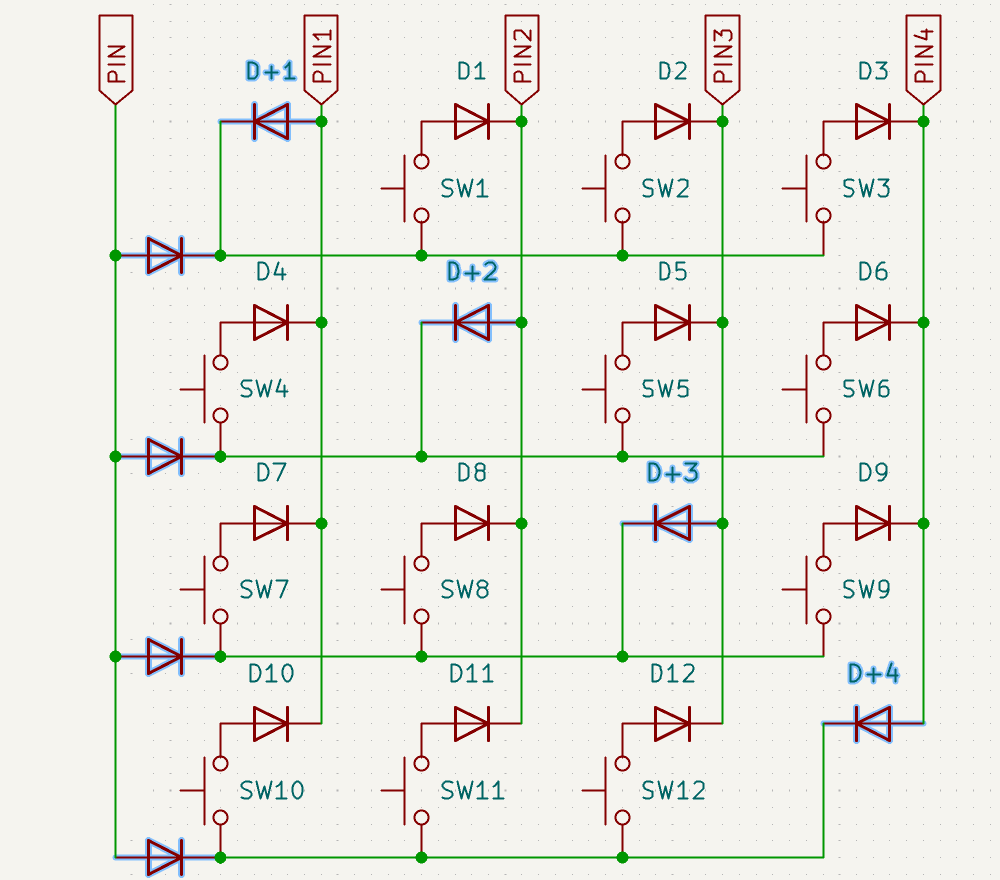
A Reciprocal Matrix

another low power proposal, by HookyKB
After publishing this post, Pete pointed me at a ZMK pull request that also tackled the issue of low power mode for an improved square matrix. This proposal starts with a different orientation of the square matrix. Pins are connected to the output segments of wires, and then connected to the input segment by a diode (facing toward the pin instead of away from the pin). This sets us up to enter low power mode with all pins set as high outputs. We then need a way to detect a keypress. We can connect all the input segments to a single pin, using diodes to prevent inputs from being directly connected to each other. This pin can be configured as an interrupt when in low power mode and disregarded at other times.
This design and the one above are the perfect duals of each other. They both accomplish the same task, as mirror opposites. If not all GPIOs are interrupt capable then this design might be preferable, otherwise there is little practical difference to distinguish them.
Conclusion
I’ve written this post to get feedback on any potential deficiencies with the low power mode proposal, and to share this idea to help us save both pins and power. I hope we will all treat power-savings as a goal in the future, even on wired keyboards.
Coda: A Personal Plea for More Pins
I fear that microcontroller board designers will use the efficiencies granted by the improved square matrix as justification to produce boards with even fewer pins broken out. For me, being able to direct wire switches for handwired split keyboards has made experimentation significantly easier. However, people keep sticking new MCUs into tiny footprints. I understand the desire to retain compatibility, but I hope designers take inspiration from the Proton-C and break out addition GPIOs on a snap-off extension (sadly, the Proton-C still only exposes 23 of 37 GPIOs). Matrix tricks are cool, but not as cool as never needing to use one :)